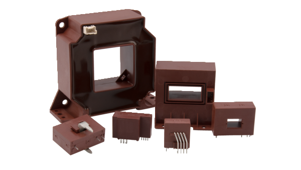
Closed-Loop Current Sensors
Current Measuring with the Highest Accuracy
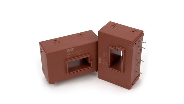
Closed-loop current sensors with VAC-invented magnetic probe as zero field detector for highest accuracy. VAC current sensors cover rated currents between 1.5 A and 1,700 A.
Benefits:
- Low rise time
- Highest accuracy of 0.4 to 0.7 %
- Frequency range DC to 200 kHz
- No temperature drift over full temperature scale
- UL listing
- Better performance than sensors with Hall-element
- Frequency converters for drives
- Photovoltaic inverters
- Wind power converters
- Charging stations for e-mobility
- Welding inverters
- Switched mode power supplies
- Robotics
General Characteristics
Standards and Regulations
Our sensors are designed according to IEC 61800-5-1 “Adjustable speed electrical power drive systems”. However, the sensors also meet many claims of other standards, such as EN 50178 “Electronic equipment for use in power installations” or EN 62109 “Safety of power converters for use in photovoltaic power systems”. Furthermore, our standard types are certified by Underwriters Laboratories according to UL508, “Industrial Control Equipment”. The category is NMTR2 (Component – Power Circuit and Motor – mounted Apparatus). VAC sensors can be found in the Files E317483 and E169721.
Validation and Type Testing
All newly created series are subjected to extensive type testing and validation. The criteria of the type tests are described in our data sheets under the headings “Electrical data: (investigated by type testing)” and “Routine tests”. The validation includes placement in damp climate, alternating temperatures in damp climate, rapid temperature changes, repeated on/off cycles, sinusoidal vibration, continuous shock, solderability and resistance to solder heat tests.
Functional Principle of the VAC Closed Loop Current Sensors
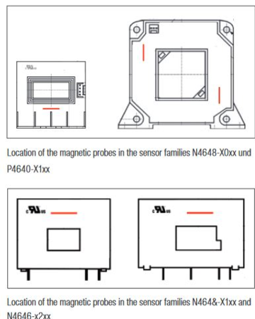
The current IP to be measured generates a flux in the soft magnetic core. The sensor electronics generates a flux in the opposite direction via the compensation current IS and controls the sum of the fluxes to zero. This is done by means of a magnetic field probe, which is located in the air gap of the core. At frequencies above a few kHz, the magnetic system consisting of the primary winding, the magnetic core and the secondary winding functions independently of the electronics as a current transformer.
The compensating current corresponds in amount and shape to the primary current divided by the number of turns of the secondary winding. A voltage can be derived from the measuring resistor. The main advantages of the closed loop current sensors are their high measuring accuracy, as well as their low rise time and wide bandwidth. VAC closed loop sensors with magnetic probe achieve an even higher accuracy over the entire application temperature range than their counterparts with Hall element.
Current Shapes
The operating currents to be measured in the power electronics are, as a rule, direct currents or alternating currents up to a maximum of a few 100 Hz with a high amplitude. They are superimposed by the switching currents of the power semiconductors, which reach into the single to double-digit kHz range and have harmonics up to the three-digit range. Their amplitude is significantly lower. Our current sensors are designed for this type of current. If the amplitude of high frequency components is permanently much greater, an excessive heating of the sensor core may occur. So, apart from the level of the current to be measured, its shape also has an influence on the losses and thus the heating of the sensor.
Positioning of the Primary Conductor in Current Sensors with a Primary Opening
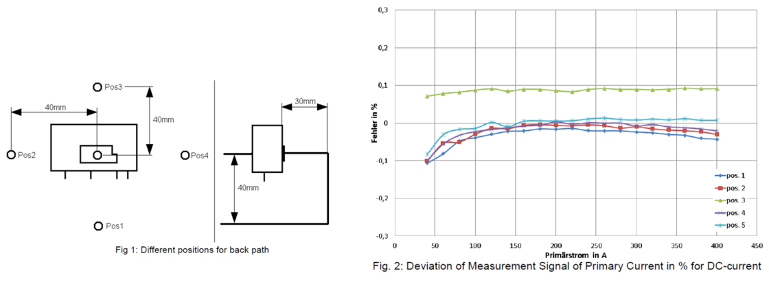
In compensation sensors, a magnetic flux generated by the primary current is detected in the sensor core and compensated for by an equally large flux of reversed polarity. Although our sensors are magnetically very robust in design, the optimal function of this measuring principle is not completely independent of the position of the conductor in the magnetic circuit, or of the position of external current-carrying conductors relative to the magnetic circuit and the zero-field probe sensor. Also of importance are the amplitude and frequency of the current. The resultant influence can affect the dynamic characteristics of the sensor, the measuring accuracy at high levels and possibly heating. The best results are achieved if the conductor is put centrally through the sensor opening and the immediate area around the current sensor is kept free of conductors carrying high currents. More information is available on request.
Conducted and Radiated Emissions
Under very unfavorable conditions, there may be an influence on the sensor by irradiation from interference signals. Low or medium-frequency interference is due to magnetic fields, for example from power chokes or transformers. High-frequency interference, usually in the range of several hundred MHz, can be injected directly into the sensor or via the connecting leads. Whether a possible high-frequency effect on the current sensor has practical consequences for the application depends on the design of, for example, the shielding of the housing. The VAC current sensors from the various series are successively tested for electromagnetic compatibility according to IEC 61000-4-3: 2010. Please contact us to inquire on the current status of the tests.
The “Offset Ripple”
Due to the principle of VAC sensors, the remnant of the internal probe signal is not completely suppressed. The frequency of this signal is 400 kHz or more. It is zero symmetrical and does not affect the measurement accuracy when integrated over at least one period. In addition, it can be further reduced with a simple low pass filter (capacitor parallel to the measuring resistor). The so-called “offset ripple” iOSS shown in our data sheets is actually not an offset.
Reference Voltage VREF in/out
Optionally the reference pin VREF can be used as input or output. Thereby the internally generated reference REFOUT can be routed as output or an external reference REFIN can be connected as input to the sensor. It is recommended to evaluate the output voltage VOUT differentially against the precise reference connected at the REFOUT output and not against GND. Doing so, lowest offset values of the current sensor can be achieved.
Product Table - Standard Closed-Loop Current Sensors
Downloads
Related Products
Differential Current Sensors
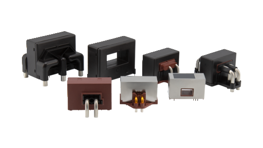
Closed-loop differential current sensors with VAC-invented magnetic probe for highest accuracy. VAC differential current (DI) sensors cover differential currents from 30 mA up to several Amps.
DI Sensor for Electric Vehicle Charging
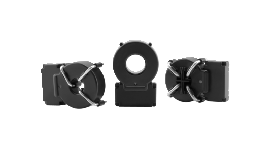
benvac is a differential current (DI) sensor specifically developed for EV-Charging. The sensor can activate an automatic shut-off in case of hazardous electrical faults (DC and AC) according to IEC 62752 or UL2231.

Power Electronics
Our power electronics solutions are comprised of current measurement devices such as closed loop current sensors and differential current sensors as well as filter cores and common mode chokes for EMC applications
